Installation

Shipping Box Contents / Required Tools

Pole Mount Option

Shipping Box Contents
  • SatVUE Remote Satellite Monitoring System
  • 1 x 90mm bolt
  • 2 x inline sensor connectors (Sensors not included)
  • Quick Start Installation Guide
  • Sensor wiring diagram (if applicable)

Required Tools
  • ∅ 50mm (diameter) pole / mast
  • Power drill and 6mm drill bit
  • 2 x 10mm spanners

Tank Mount Option

Shipping Box Contents
  • SatVUE Remote Satellite Monitoring System
  • 4 x screws
  • 1 x integrated ultrasonic level sensor
  • 1 x inline sensor connector (Sensor not included)
  • Quick Start Installation Guide
  • Sensor wiring diagram (if applicable)

Required Tools
  • Power drill and ∅ 50mm (diameter) hole saw
  • #2 Phillips screwdriver or 100mm #2 Phillips screwdriver bit

Mounting Location

Observe the following guidelines before proceeding with installation

  • the SatVUE should be mounted in clear view / line of sight with the sky, preferably at the highest point and free of obstruction from the immediate surroundings / environment.
  • ensure that the SatVUE is mounted level - spacers may be required (not supplied) when mounting the tank mount version.
  • do not mount the SatVUE where water may build-up or collect.
  • do not mount the SatVUE close to other electrical equipment due to possible radiated and/or conducted electromagnetic interference.
  • do not mount the SatVUE close to radar or other communications antennas. Use the following guidelines:
    • 1 m from VHF/UHF antenna
    • 3 m from loop antenna
    • 4 m from MF/HF antenna
    • 5 m from other satellite antennas
    • Not within a radar beam

Solar Panel Angle

If your SatVUE model includes the solar panel option, ensure that the terminal is mounted in such a way that the solar panel receives maximum exposure to sun during daylight hours. To ensure this, the latitude and longitude of the site location must be established when determining the angle and positioning of the solar panel.

An online tool is available to assist you in determining the correct position and angle of the solar panel for your specific location. Visit www.satvue.com.au/solar-panel for more information.

SatVUE Pole Mount Option


To mount the SatVUE Pole Mount unit, the following prodecure should be followed:

  • secure the ∅ 50mm pole / mast in the desired location.
  • remove the 90mm bolt from the base-mount of the SatVUE and place the SatVUE atop the ∅ 50mm pole / mast.
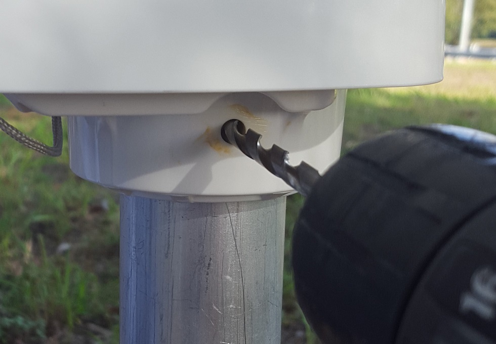
  • use the two (2) pre-drilled holes in the base-mount of the SatVUE as a guide to drill the required holes into the ∅ 50mm pole / mast.
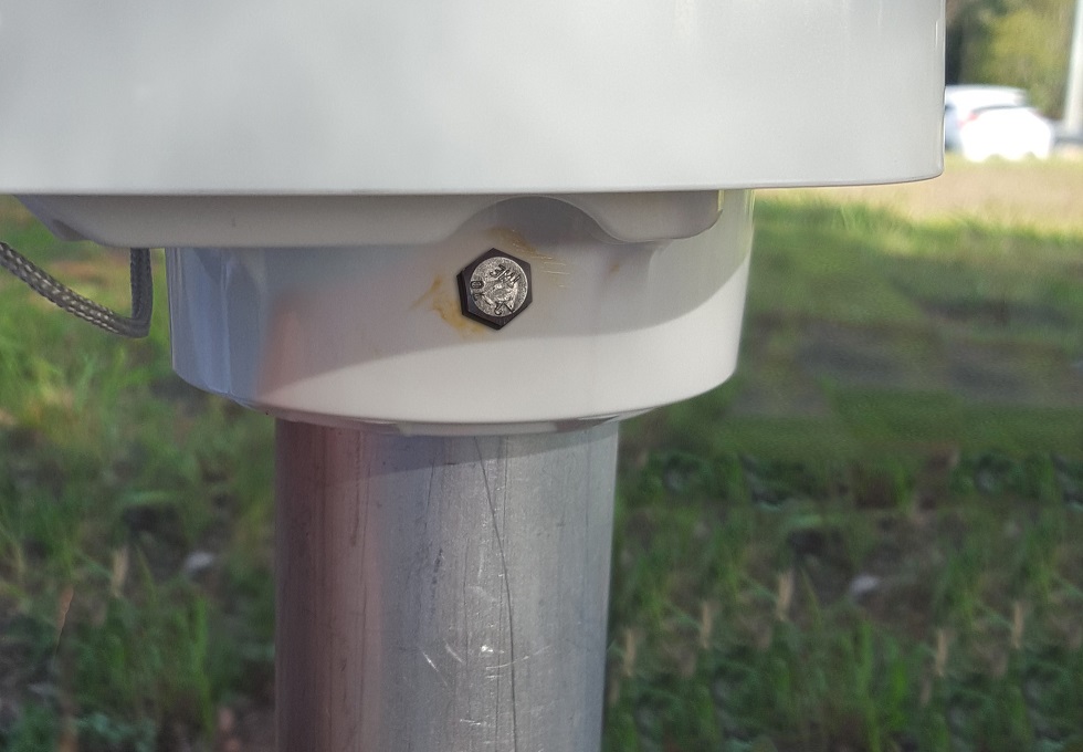
  • insert supplied 90mm bolt through the SatVUE base-mount and pole / mast and secure into position.
  • connect your sensor(s). This will automatically power the SatVUE on. A red LED on the front of the SatVUE will activate. Refer to LED legend below, to determine the meaning of the LED flashing sequence.

SatVUE Tank Mount Option

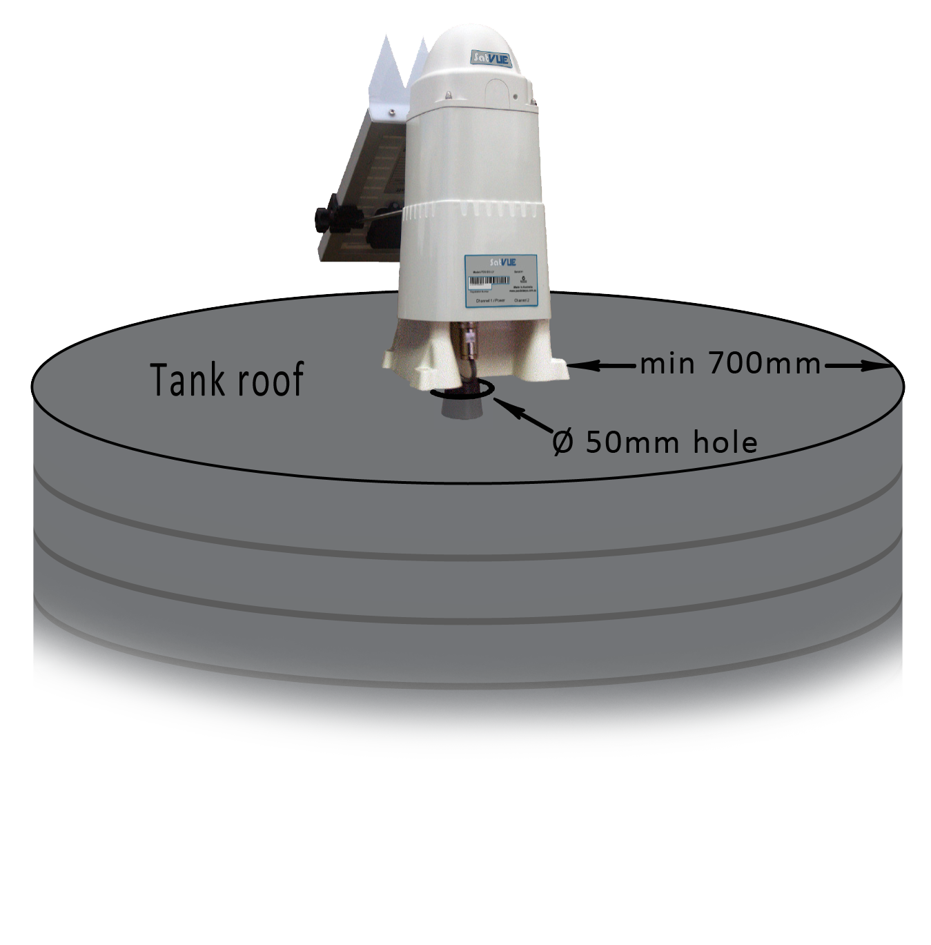
To avoid interference between the ultrasonic level sensor and the walls and / or level-flotation device of the tank, the following should be observed in regards to siting the SatVUE Tank Mount option:

  • mount the SatVUE as close to the centre of the tank roof as possible. Ultimately, a distance of at least 700mm from the edge of the tank should be observed.
  • avoid mounting the SatVUE directly on the tank access panel.
  • ensure the SatVUE is mounted level - spacers may be required (not supplied)

To mount the SatVUE Tank Mount unit, the following prodecure should be followed:

  • use the supplied mounting template to mark out the 4 x screw holes for the base mount and ∅ 50mm (diameter) hole for the ultrasonic sensor.
  • using the hole saw, drill a ∅ 50mm (diameter) hole into surface of the tank roof enabling the ultrasonic level sensor to pentrate into the tank.
  • connect the sensor into Channel 1. This will automatically power the SatVUE on. A red LED on the front of the SatVUE will activate. Refer to LED legend on pg.2 of this guide to determine the meaning of the LED flashing sequence.
  • secure the base of the SatVUE to the tank using the 4 x supplied screws. Spacers may be required (not supplied) to ensure the device is level.

LED Legend

With the sensor(s) connected, the SatVUE will commence connection to the IsatData Pro Satellite Network.

During this connection process, the red LED on the front of the device will display a sequence of flashes per 30 seconds.

Refer to the following legend as a guide to the red LED flashing sequence:

Step 1: 3 flashes every 30 seconds Obtaining GPS fix
Step 2: 2 flashes every 30 seconds Network registration in progress
Step 3: 1 flash every 30 seconds Successful connection obtained (system online)

Should the following flash sequences occur (4 and 5 flashes), consider location and environment in relation to the section in this guide entitled ‘Mounting Location - observe the following guidelines when selecting the mounting location’ (pg.1). The SatVUE may need to be moved to a more suitable location.

4 flashes
every 30 seconds

Indicates the percentage of successful receives (communication) falls below 25% between the SatVUE and the IsatData Pro Satellite Network.

5 flashes
every 30 seconds

Occurs when communication between the SatVUE and the IsatData Pro Satellite Network has been lost.

Note: contact your retail provider if issue persists.